|
FORD TRANSIT TEST RIG
Please use our A-Z INDEX to navigate this site or return HOME
|
|
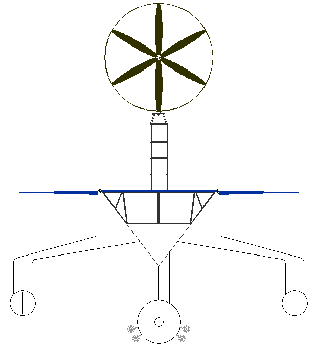
CAD diagram showing solar wings of the (proposed) Elizabeth Swan design unfolded to their horizontal position and the wind turbine mast raised - HAWT example. The system is identical to that built in smaller scale for development purposes, using a Ford Transit as the donor vehicle.
PRACTICAL EXPERIMENT 2019
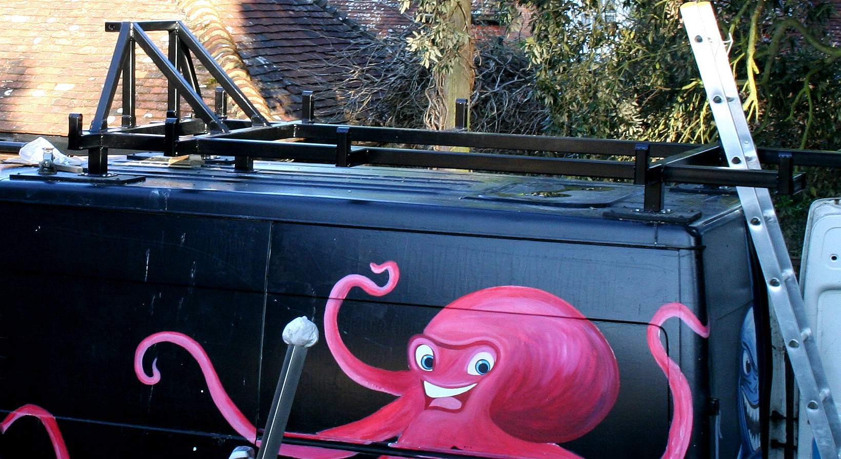
With the generous help of an engineering student from Belgium, the Foundation funded the development of a test rig designed to improve knowledge of the proposed wind turbine mast and folding solar wings, part of the design concept of the Elizabeth Swann. A Ford Transit was chosen as the donor vehicle to give us a mobile platform, where workshop facilities are modest and space limited. Meaning we could work outside.
This also means that university students might work on this project at their campus. The vehicle being mobile, to enable delivery to other locations, and of course, testing in various geographical locations.
ARRAYS - BOOM - MASTS - INTERIOR - PAINTING - ROBOTICS - WELDING - WIND TURBINES
As with the design of the boat, we used a CAD program to work out the angles, to be sure the Transit van could contain and support the test rig, and then to dimension the parts for cutting steel sections and then to fabricate the parts, using MIG welding equipment for joining. We only had 3 months from start to finish to complete this phase of the test rig, including design time. This was not really long enough to complete, but gave us enough time to build and install a frame, for completion in the future as funds and time allows. We are hoping to interest other advanced engineering/robotic (mechatronics) students, perhaps as part of coursework or as a group development project.
Our guest from Liege, spent another 3 months in Belgium working on a computer program to control the lifting and lowering of the boom, in relation to safe wind speed using a controlled simulation. This was not taken forwards as a complete or demonstrable model, or fitted to the vehicle. And did not include operation of the solar panels in harmony with the wind turbine.
Hence, this is work in progress - or rather - work needing to be done. Quite a lot of work, where the solar panels arrays were never constructed (though all components sourced and in stock including the solar panels). There are CAD drawing to enable completion (fabrication) and we have the hydraulic motors, but not the gearing. That would need to be designed using off the shelf chains and cogs, with adaptors specially machined.
The Foundation will fabricate the panels in our own workshops, and install wings and hydraulic motors. Or, students can gain some practical experience, if preferred.
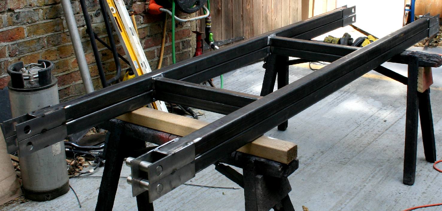
WELDING: Fabricating the prototype masts in steel.
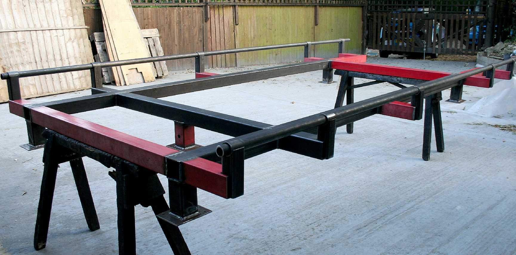
FABRICATION: Jigging the bearings for the solar-wing shafts.
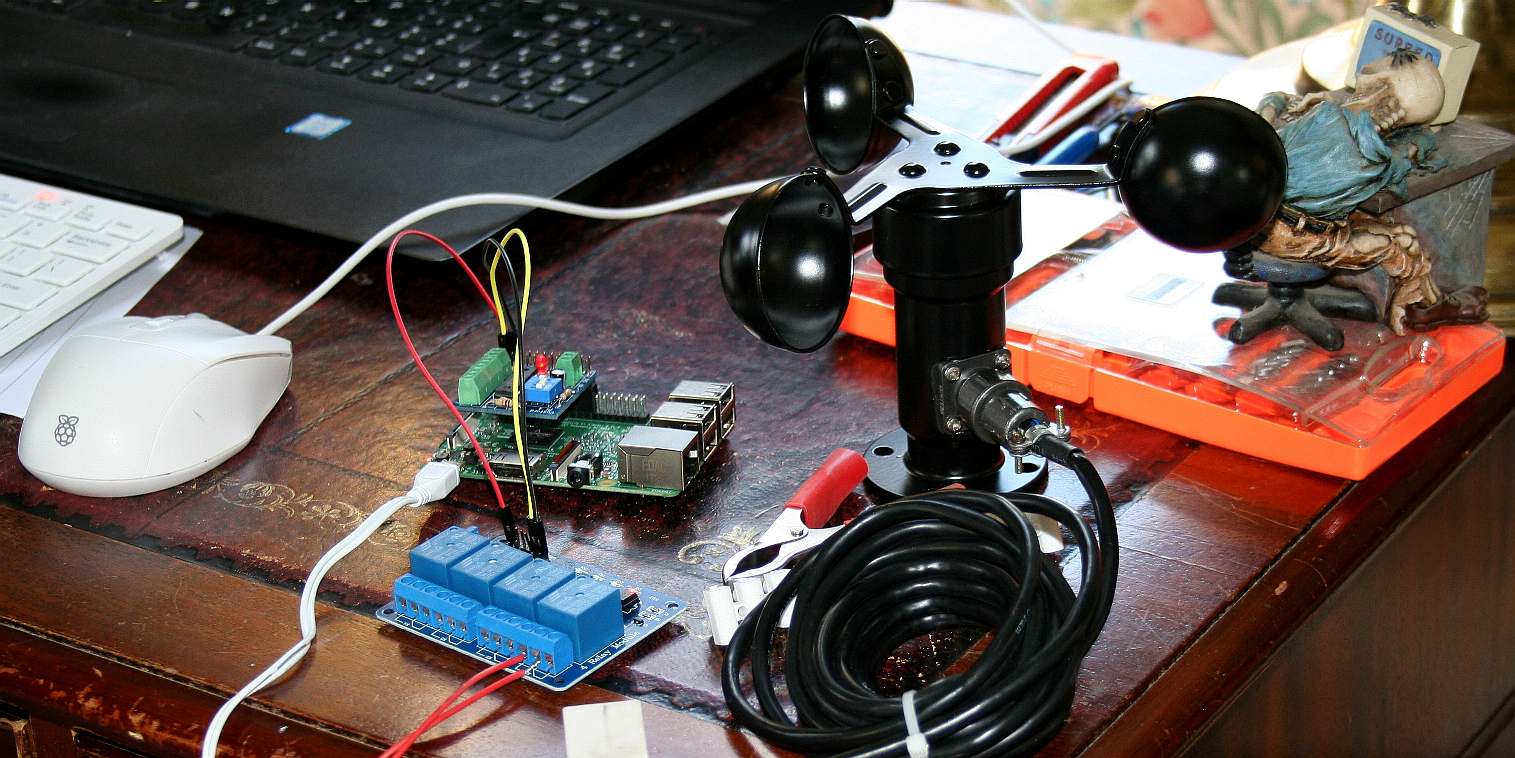
RASPBERRY: Programming a Pi to control the mast raising/lowering with measurements of wind speed via two anemometers for positional safety.
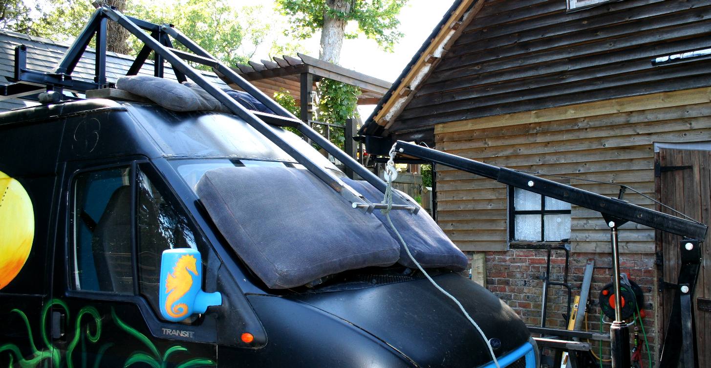
MAIN FRAME FITTED: The steel structure was bolted to the donor van.
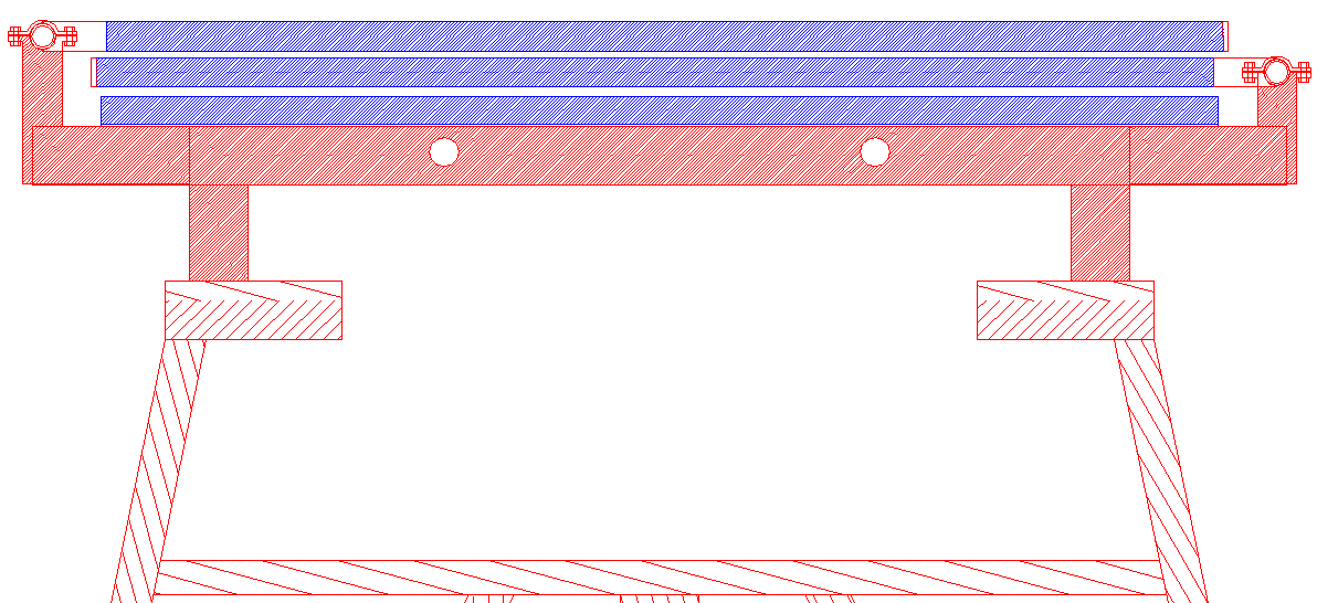
WINGS FOLDED: Diagram of the roof mounted frame, showing solar wings folded against high winds.
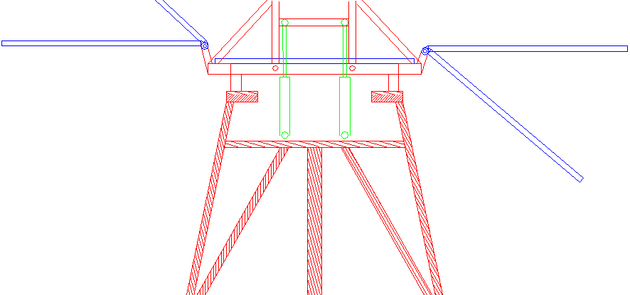
WINGS OPEN: Diagram of the roof mounted frame, showing solar wings folded opened and angular changes for tracking the sun.
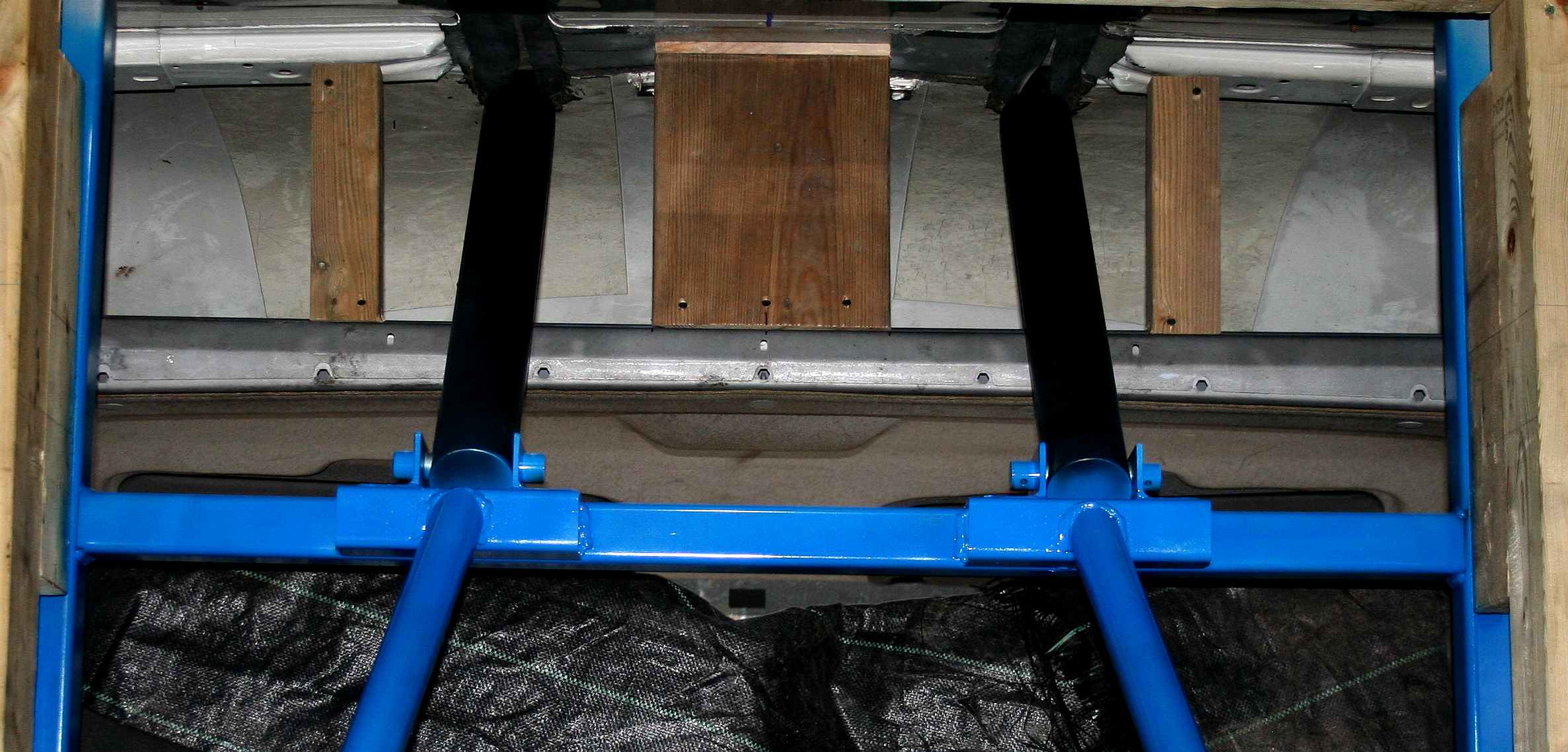
LOAD TRANSFER: To support the roof loads from above, a timber frame was fitted inside the van, also to act as a jig for a steel frame.
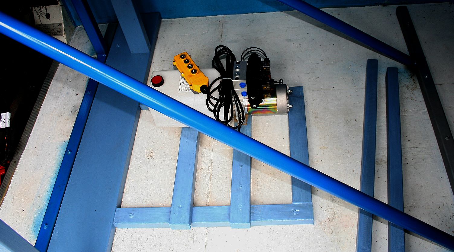
TRIANGULATION: Steel cross bracing was added inside the vehicle, and another timber frame bolted to the floor to be able to mount the hydraulic power packs.
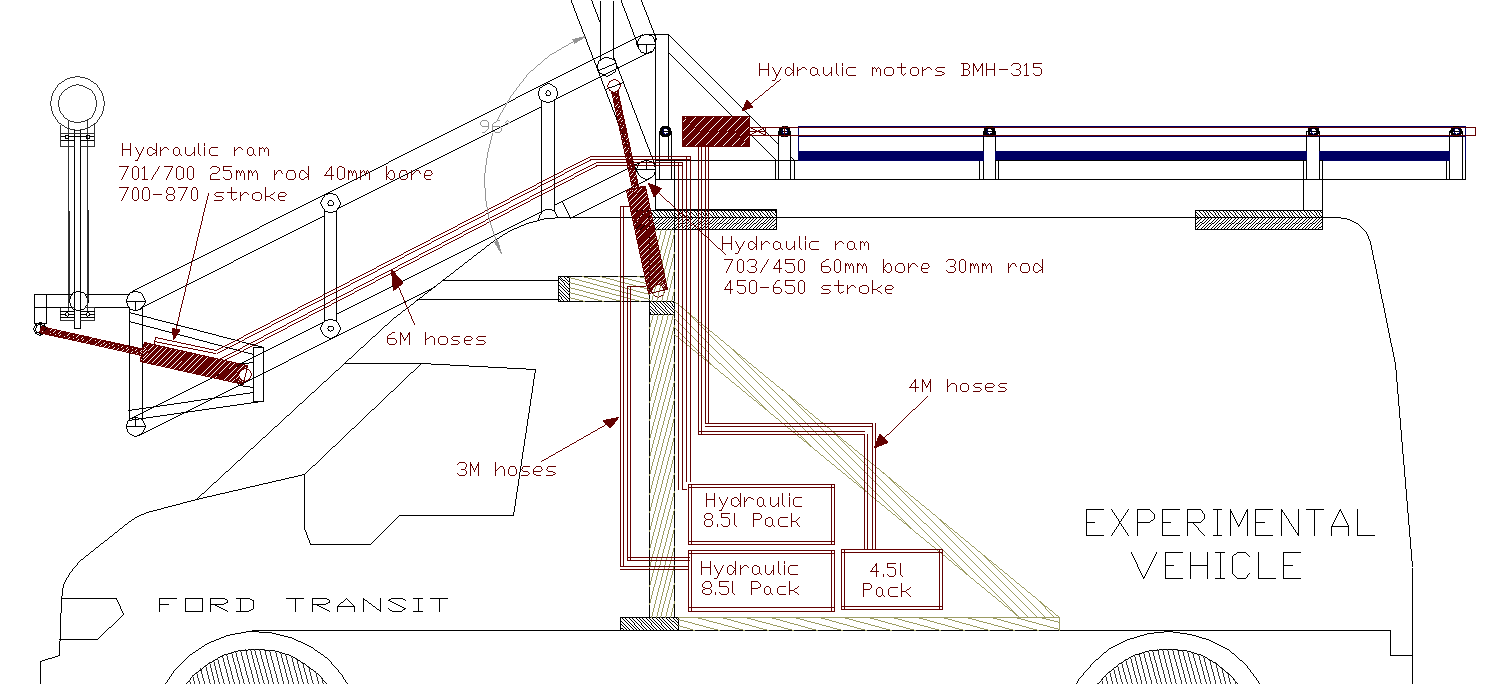
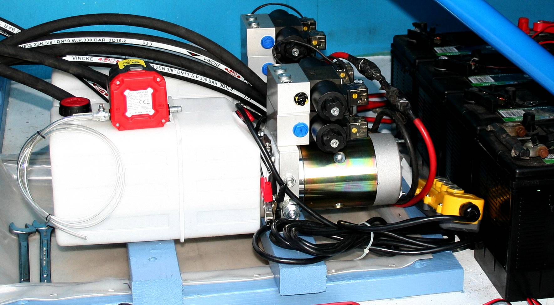
HYDRAULICS: Twin power packs bolted in. One for mast raising lowering, the other for solar panel tracking and furling operations. Four medium size, leisure batteries are installed for the solar panels and wind turbine to charge, the stored energy also being used to power the electro-hydraulic pumps.
RAMS: Twin hydraulic rams were fitted, going through the roof of the vehicle, presenting a sealing problem, that was partially solved with rubber gaiters. The dribble remaining is captured by the existing cabin roof, that fortunately is galvanized.
MAST INSTALLATION: The masts were installed, to make sure they would lift and lower, and the bearings worked satisfactorily. The van was driven locally to be sure it could handle the top-heavy installation. It coped magnificently. Well done Ford.
|
|
|
This website is Copyright © 2021 Jameson Hunter Ltd
|