|
HULL DRAG - POWER ESTIMATES
Please use our A-Z INDEX to navigate this site or return HOME
|
DESIGN WEIGHT - It's very different working in paper and cardboard, compared to marine alloys. We should also consider that our model tests will mostly be conducted in fresh water which is 1 kg/liter as opposed to 1.025 kg/liter for seawater - meaning that the full size vessel will have that advantage also, unless that is the operators intend navigating mainly in rivers.
Many boat designers have grappled with the fact that the power required to push a hull through the water increases approximately as the cube of the hull speed, so that very small performance increases need major power boost, as the boat approaches its hull speed.
The only exceptions are stepped planing hulls and foilers that cheat the rule, where once an energy hump is overcome, the boat lifts up, creating hydrodynamic lift to ride over the water (usually most uncomfortably in deep V racing hulls) to reduce drag (viscosity resistance and wetted area). Of these designs foils (underwater wings) give the best results and smoothest ride. They are however, unsuitable for most commercial craft, where there is no substitute for length and frontal area reduction.
Hence, hull design is paramount, and choosing the correct format for a purpose is all important. Generally, this comes down to cost, as with all engineering challenges.
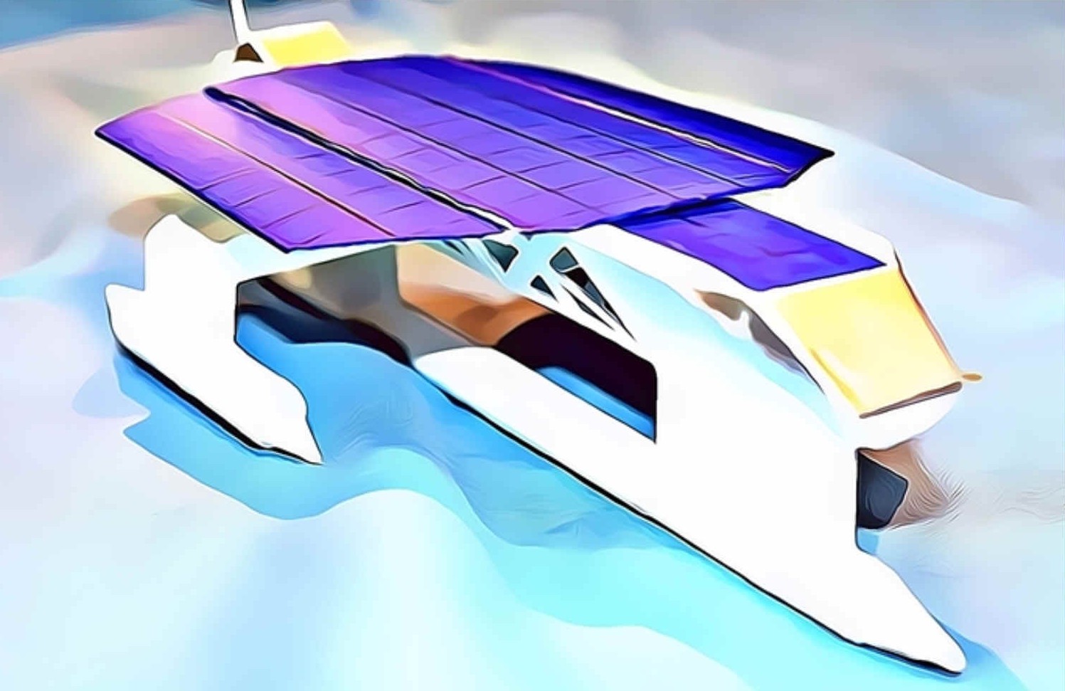
We have selected a single central wave piercing hull stabilized by outriggers as a trimaran, because a long thin hull needs less energy to ply the waves. Typically, slender hulls are prone to roll instability with interior design challenges that naval and luxury yacht owners would not suffer. Hence our wide track sponsons, that in our case rarely touch down with regular running and active deployment of retractable hydrofoils, allows us to bend the rules. But we are prepared to suffer interior space limitations in the quest for speed.
The Elizabeth Swann's hull includes:
a) Ultra light superstructure purposed designed to harvest energy from nature via b) and c) below,
b) Solar wings that track the sun and fold for storms, in concert with
c) A turbine generator on a mast that tracks wind conditions and furls for storms.
Drag is a function of hull design, that includes the area and shape of the nose (or prow) and transom, and the area and shape of the superstructure. This gives us the total drag of the vessel, ignoring violent weather pressures for now. Reducing frontal area helps considerably, but presents a challenge for the interior designer.
The graph below is derived from the draft specifications of the Elizabeth Swann as first conceived, but is a useful starting point - and would suffice, provided we can meet our weight and hull wetted area targets. That is down to innovative design, rather than exotic materials. We'll keep the exotic materials in our back pocket for now.
KNOTS Vs kW - A hull drag curve is dependent on many variables, such as conversion efficiency (70% assumed). You can see from the above graph, that to reach our 10 knot goal with a conventional displacement hull, we need around 27kW of continuous energy across the Atlantic, for which we'd have to have ideal conditions. A more easily achieved target would be 7.5 knots, requiring 14.5kW continuous. While the present record of 5.3 knots, held by PlanetSolar, could be equaled with just 7.5kW of energy. As speed and drag rise we can flatten the curve with the deployment of hydrofoils, should our development team determine (as expected) that there will be a significant performance improvement with such high-tech inclusion - as depicted below.
HYDROFOIL V WINGS - CALM RUNNING - In moderate seas with a following wind and the sun overhead, the cantilevered sponsons of the Elizabeth Swann may be lifted out of the water, with the V-foils running below the water surface. Small 4-point sailing craft benefit the most from hydrofoils, overcoming their speed/length ratio restrictions as they take to the air, in the process achieving wind speed. Whereas, larger craft reach twice wind speed for long periods, dependent on conditions. Design Copyright © February 2021.
WHAT SIZE MOTORS?
Compared to I.C. engines and small diameter propellers, as with an outboard engine, an electric drive train can improve the conversion of energy to propulsive force, where synchronous dc machines are now very efficient at higher voltages. Propeller design is very important, but is often overlooked, where large diameter, thin, twin-blades revolving at low rpm are more efficient, but may not be practical for commercial ships that cannot achieve the thrust in relations to tonnage and still enter ports.
The latest shaft-less rim drives (or jet thrusters) potentially offer even more efficiency.
To be able to size the motors we need to know the displacement of the vessel, the length and the hull shape - including the lead in and out angles and the desired operating speed. This information will allow us to calculate the hull drag with some degree of accuracy. It has been established that at low speeds frictional resistance is the greater component of hull drag. As speeds rise (above a speed/length ratio of 1.05) wave making drag becomes the predominant force.
BHP= 2xRxV/550
Where R is the resistance in pounds and V is the speed or velocity of the vessel in feet per second. Just multiply knots by by 1.68 to get ft/s. Hence, 8 knots is 8x1.68 = 13.44 ft/s.
Hence a 5 ton boat would generate (5x11) 55 lbs of drag.
If we apply our formula: BHP = 2x55x4x1.68/550 then BHP = 1.34.
The same boat at a speed/length ratio of 1.4 (hull speed) and 7 knots will raise frictional resistance to 99 lb/ton or in this example (5x99) =495 lbs.
Therefore: BHP = 2x495x7x1.68/550 then BHP = 21.2
Thus to achieve a modest 3 knot increase in speed, power requirement has gone up nearly 16 times (calm water figures). Sorry for this mix or imperial and metric
units, our conceptual designer is old school, and these calculations are
simplified, compared to other methods of estimating boat speed and
energy required.
All of these examples would require the same horsepower per ton - though speed has nearly doubled. Clearly then a solar boat with limited power should be long and thin to gain the maximum performance. We should also consider that the shape giving the least wetted area is the arc of a circle, but that such a shape is not practical except in multi-hulls.
DRAFT SPECIFICATIONS
Theoretical displacement: 30,000 - 45,000 kilograms (target) in 5083 alloy.
LINKS & REFERENCE https://www.radiosailingtechnology.com/index.php/hulls/estimating-the-hull-drag-of-an-iom-yacht-august-2014 http://solarnavigator.net/wave_drag_boat_design.htm http://solarnavigator.net/propellers.htm http://www.solarnavigator.net/hull_drag.htm https://forums.ybw.com/index.php?threads/working-out-hull-drag.272540/
|
|
Please use our A-Z INDEX to navigate this site or return HOME
This website is Copyright © 2021 Jameson Hunter Ltd
|